Galvanized and Hot Dip Galvanized Coatings

Galvanized and Hot Dip Galvanized Coatings

Galvanized and Hot Dip Galvanized Coatings

I. Introduction

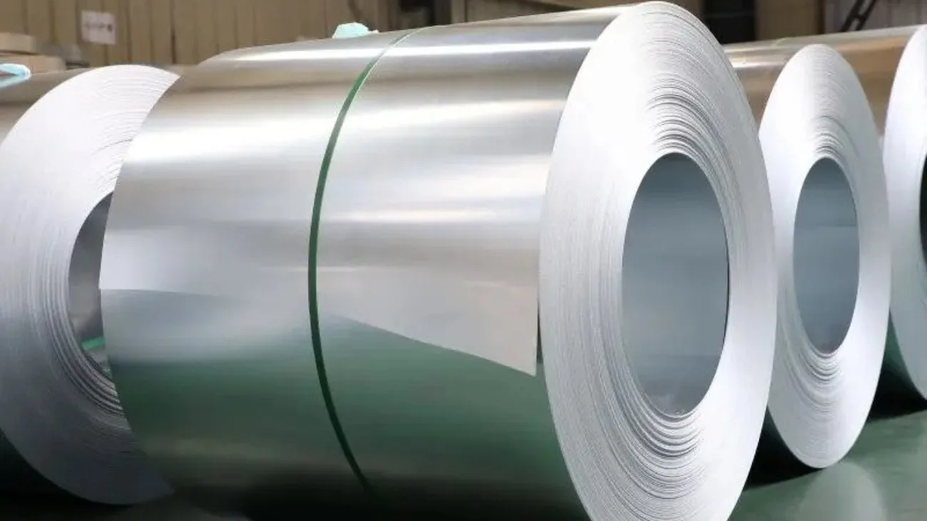
Galvanized and hot dip galvanized coatings are commonly used for corrosion protection of solar mounting structures. The choice between galvanized solar mounting frames and hot dip galvanized solar rails depends on factors like cost, longevity, and ease of application.

The key differences between galvanized and hot dip galvanized coatings for solar mounting structures:

  • Type of zinc coating
  • Surface preparation requirements
  • Resulting surface texture and finish
  • Corrosion resistance performance

A summary of the differences is provided in the table below:

CriteriaGalvanized CoatingHot Dip Galvanized Coating
ProcessElectroplating, thermal sprayHot dip immersion in molten zinc bath
Surface preparationDegreasing, picklingDegreasing, pickling, fluxing
Coating textureSmooth, sharp finishRough finish
Corrosion protectionModerateExcellent

Galvanized coatings are applied by methods like:

  • Electroplating
  • Thermal spray of molten zinc
  • Mechanical plating

These provide a smooth, uniform finish on solar mounting components like frames, brackets, and fasteners.

Structura will provide a Hot dip galvanizing involves dipping prepared steel components in a bath of molten zinc to form zinc-iron alloy layers. This provides excellent corrosion resistance but results in a rough texture.

By understanding the key differences, solar project developers can select the optimal corrosion protection method for their specific solar mounting requirements.

Click Here For More Detail

II. Galvanized Coatings for Solar Mounting Structures

Galvanized Coatings for Solar Mounting Structures

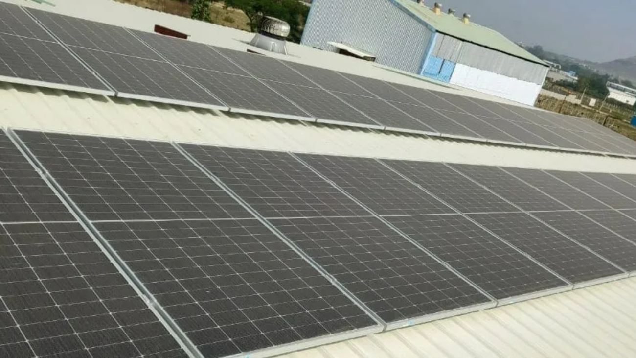
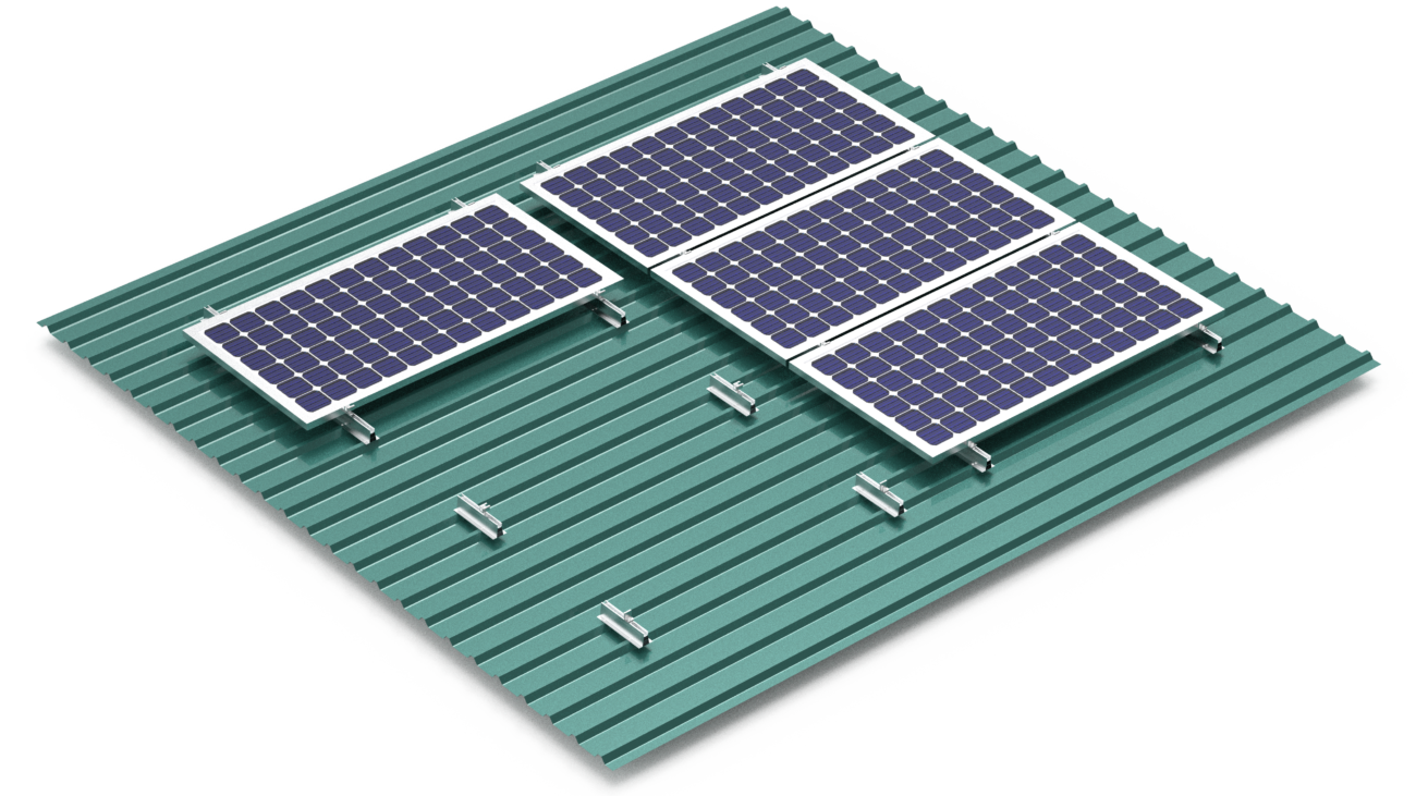
Galvanized coatings are commonly applied to solar mounting components like:

  • Solar module frames
  • Solar array brackets
  • Solar structure bolts

Galvanized coatings provide moderate corrosion protection with a smooth finish.

The main galvanizing processes are:

  • Electroplating – Uses electric current to deposit zinc onto solar components
  • Thermal spray – Sprays molten zinc onto solar panel parts
  • Mechanical plating – Deposits zinc through mechanical energy

Benefits:

  • Lower cost
  • Uniform smooth finish
  • Good for steel solar anchors and mounting posts

Limitations:

  • Less corrosion protection than hot dip galvanizing
  • Not suitable for high corrosion environments

Overall, galvanized coatings are cost-effective for solar structures not exposed to extreme weather conditions. The smooth finish also allows efficient installation of solar modules.

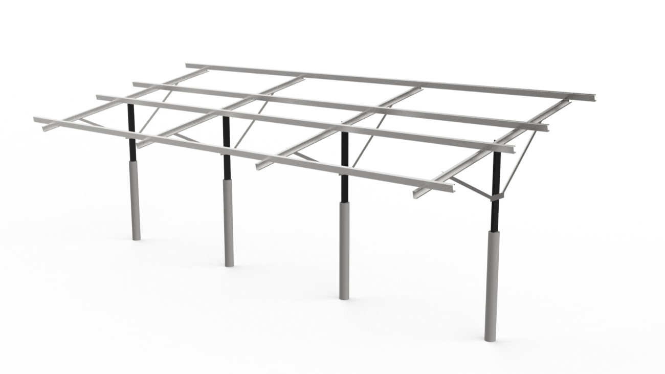
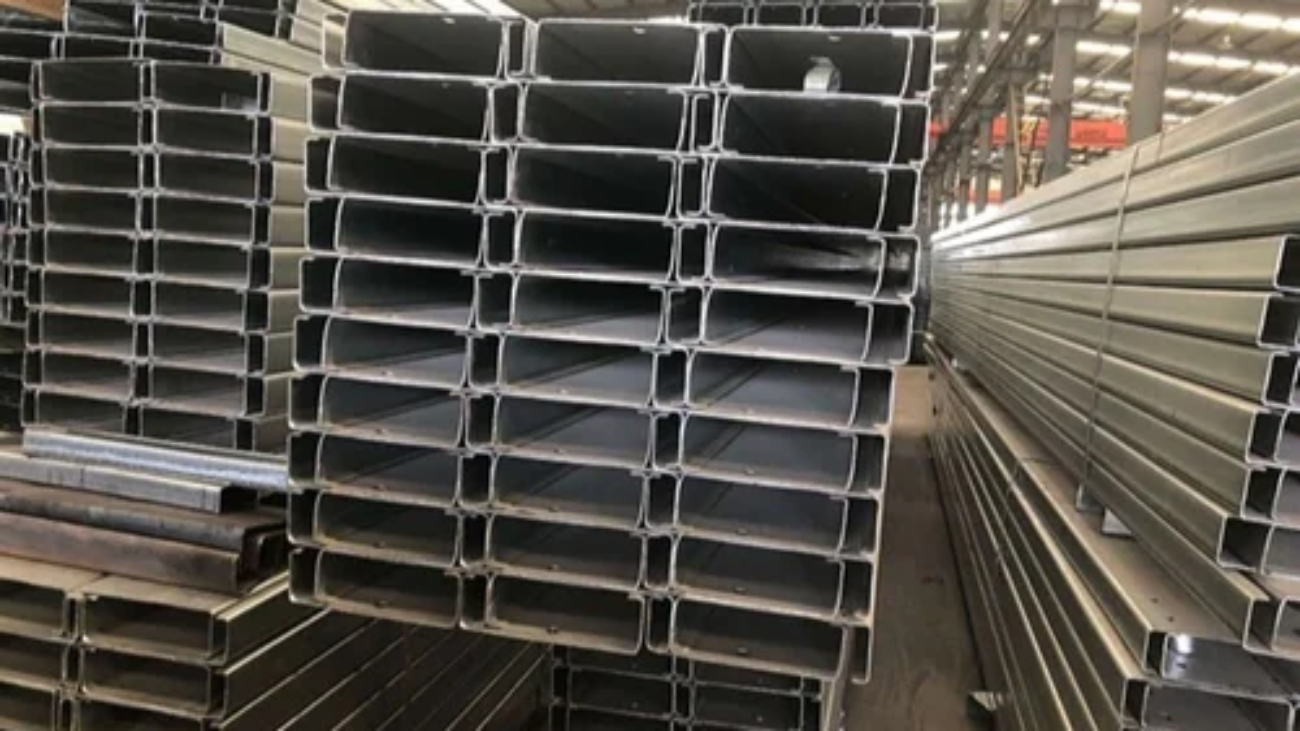
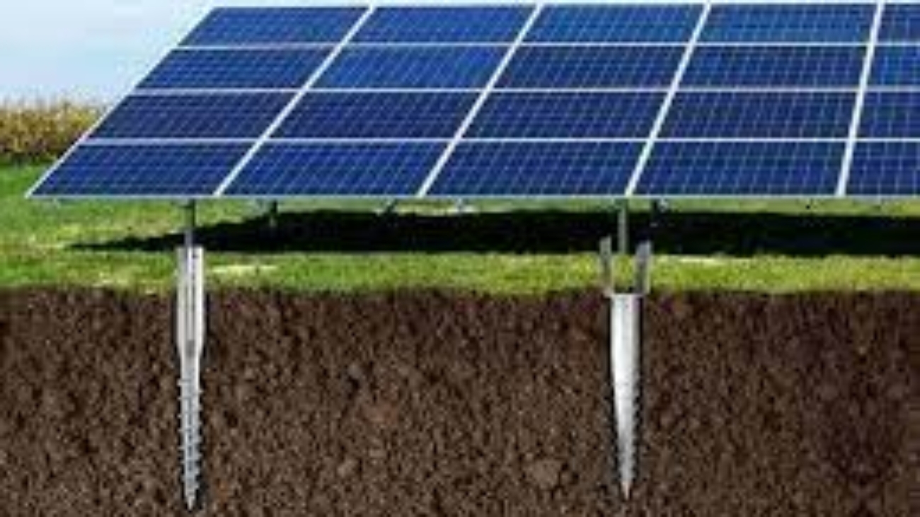
III. Hot Dip Galvanized Coatings for Solar Arrays

Hot Dip Galvanized Coatings for Solar Arrays

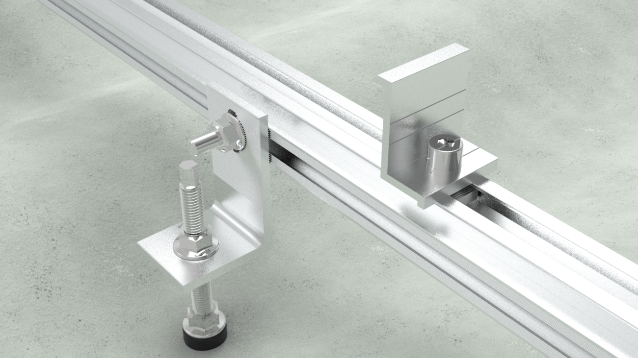
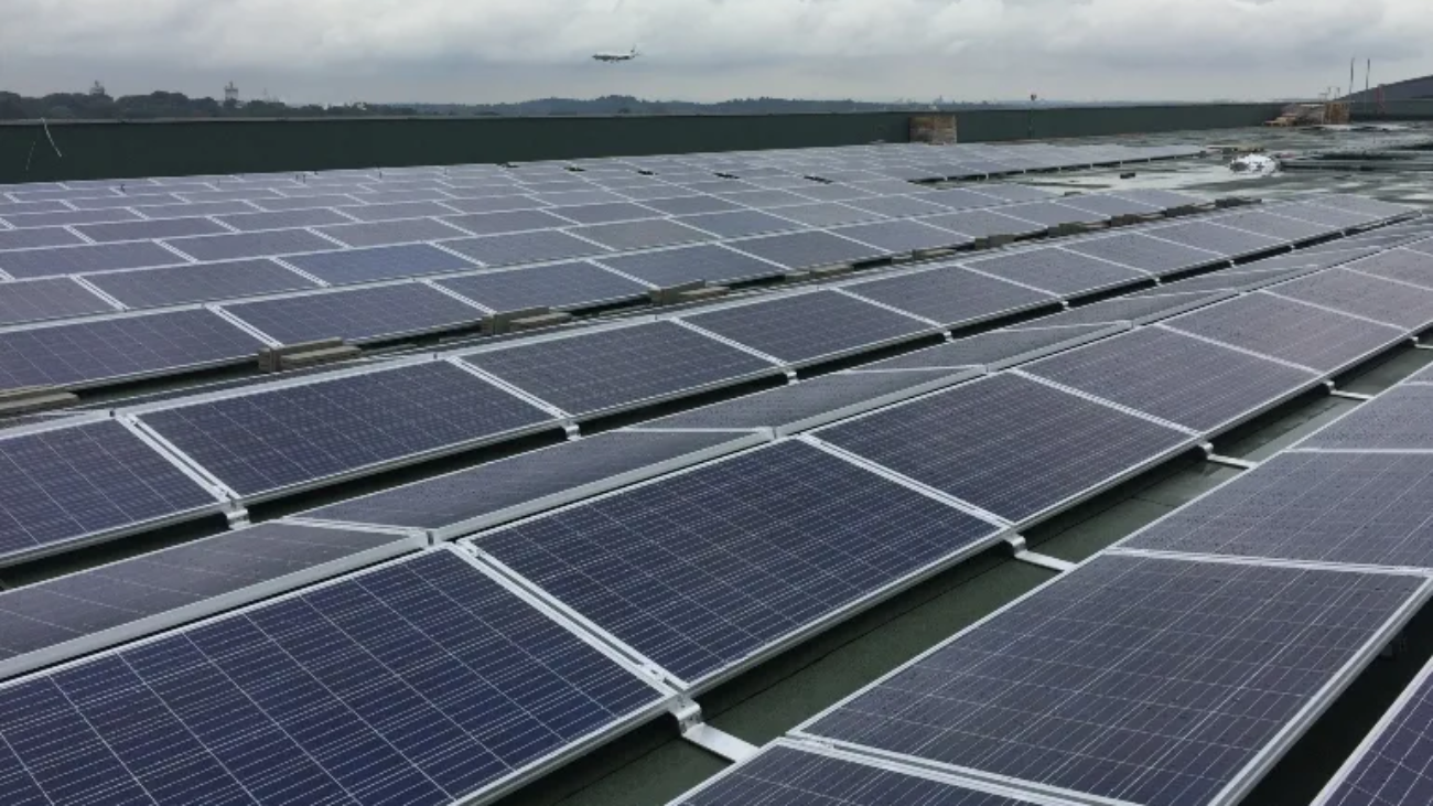
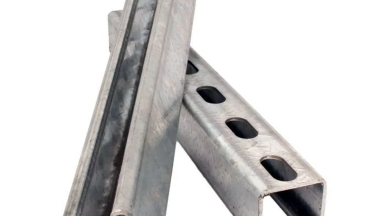
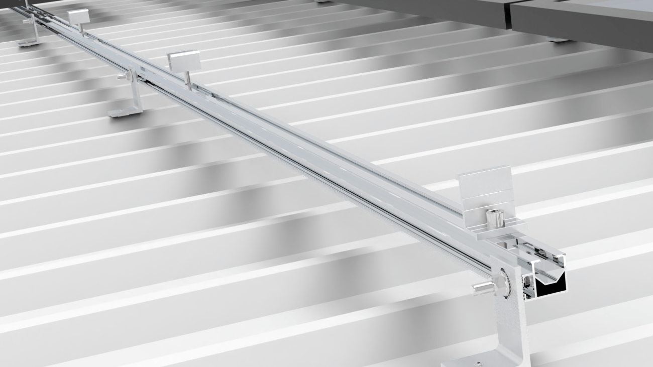
Hot dip galvanizing is commonly used to protect large solar array structures and components like:

  • Solar array rails
  • Solar panel clamps
  • Solar tracking braces

The hot dip galvanizing process involves:

  • Surface preparation – Degreasing, pickling, and fluxing
  • Dipping in molten zinc bath to form zinc-iron alloy layer
  • Inspection of coating quality

Benefits:

  • Excellent corrosion resistance
  • Withstands extreme weather environments
  • Long service life for solar mounting hardware

Limitations:

  • Rough surface finish
  • Higher cost than galvanizing

Hot dip galvanized coatings provide maximum corrosion protection for large solar arrays and mounts installed in coastal, industrial, and severe climate environments. The service life can exceed 25 years.

IV. Surface Preparation of Solar Mounting Components

Proper surface preparation is essential prior to applying galvanized or hot dip galvanized coatings on solar mounting hardware. The main preparation steps include:

  • Degreasing – Removes oil, grease and dirt from surfaces like:
  • Solar module frames
  • Solar tracking drive arms
  • Solar clamp bolts
  • Pickling – Uses acid solution to remove iron oxide and mill scale from:
  • Solar structure I-beams
  • Solar foundation anchor bolts
  • Fluxing (for hot dip galvanizing) – Applies protective flux coating to prevent oxidation of steels like:
  • Solar torque tube shafts
  • Solar array roller pins

Effective surface preparation allows maximum adhesion and corrosion protection from the galvanized or hot dip galvanized coatings.

It is crucial to remove all traces of oil, grease, rust, scale and other contaminants from the steel surface through thorough cleaning, pickling, and fluxing steps.

This ensures optimal zinc coverage and corrosion resistance for the solar mounting hardware over decades of service.

V. Corrosion Protection with Zinc Layers

The key purpose of galvanized and hot dip galvanized coatings is to provide corrosion protection for steel solar mounting components.

The zinc coating protects the underlying steel in two ways:

  • Barrier protection – The zinc coating forms a physical barrier preventing corrosion agents like oxygen, moisture and chloride ions from reaching the steel.
  • Cathodic protection – If the zinc coating gets scratched, the zinc sacrifices itself and corrodes first instead of the underlying steel. This is due to the electrochemical properties of zinc.

During hot dip galvanizing, iron on the steel surface reacts with the molten zinc bath to form protective zinc-iron alloy layers.

Prior pickling to remove iron oxide and mill scale allows better contact between the steel and molten zinc to form uniform alloy layers.

The resulting zinc coating provides excellent corrosion resistance for steel solar mounting hardware, even in harsh outdoor environments with high humidity, salt spray or industrial pollutants.

Proper surface preparation and quality hot dip galvanizing processes optimize the protective zinc layer thickness and life span.

VI. Finishing and Inspection of Solar Mounts

The final steps for galvanized and hot dip galvanized solar mounting components involve:

  • Finishing to achieve the desired surface texture
  • Inspection to ensure coating quality
  • Galvanized coatings have a smooth, sharp finish suitable for:
  • Solar array frames
  • Solar tracker gears
  • Solar PV module clamps

The smooth finish allows easy cleaning and maintenance.

Hot dip galvanizing produces a rough surface finish. The zinc-iron alloy layers form crystals that grow outward as spiky dendrites.

This rough texture provides optimal adhesion for paints and sealants when applied on:

  • Solar torque tubes
  • Solar support strut channels
  • Solar tracker rails

Thorough inspection verifies coating thickness, integrity and uniformity.

The visual contrast between galvanized and hot dip galvanized finishes provides a quick way to identify the corrosion protection method used on solar mounting components.

Proper finishing and inspection ensures long-lasting weather resistance and durability.

VII. Conclusion

Both galvanized and hot dip galvanized coatings offer effective corrosion protection for steel solar mounting structures.

Galvanized coatings provide good weather resistance at lower cost for solar components like:

  • Frames
  • Brackets
  • Fasteners

Hot dip galvanizing is the optimal choice for heavily loaded structural solar mounts and arrays in harsh environments, including:

  • Coastal areas
  • Industrial zones
  • Deserts

Proper surface preparation, zinc coating method, quality control and finish are crucial to achieve the desired longevity and return on investment.

By selecting the appropriate galvanizing method for the solar application and environment, developers can minimize maintenance costs while maximizing power output over decades.

Regular inspection of zinc coatings enables proactive maintenance to avoid any coating damage or corrosion issues.

Overall, both galvanized and hot dip galvanized treatments provide reliable, low-maintenance corrosion protection for a wide range of solar power projects.

Hanger Bolt Solar Mounting System

Hanger Bolt Solar Mounting System

Hanger Bolt Solar Mounting System

 I. Introduction

Hanger bolts are an essential component of solar mounting systems installed on rooftops. They serve as the structural attachment between the solar panels and the roof surface.

Hanger bolts consist of:

  • A threaded bolt
  • Collar nuts and washers
  • An EPDM rubber grommet seal
  • A mounting plate with a slot

They are made of durable stainless steel and aluminum.

The key characteristics of hanger bolts include:

FeatureDescription
AdjustabilityOffer variable lengths and angles to mount panels
Structural integrityWithstand wind, weather and meet building codes
Watertight sealingRubber gasket protects roof from leaks
Solar Mounting Hanger Bolt Systems

Hanger bolt kits contain all the fittings needed for a complete solar panel installation:

  • Hanger screws
  • Mounting rails
  • Mid/end clamps

We provide a secure and user-friendly mounting system with professionals and DIY installers.

When paired with compatible solar racks and rails, hanger bolt sets enable angled or flat installations on various roof types like singles, tiles, and metal roofing profiles.

By elevating and securely fastening solar modules, hanger bolts play a critical role in durable and high-performing rooftop solar energy systems. Their adjustable nature allows for tailored positioning to maximize solar capture potential.

II. Components

Hanger bolt solar mounting systems comprise three main components that work together:

Hanger Bolts

Hanger bolts

Hanger bolts are the metal fasteners that attach solar panels and rails to the roof structure. Key features include:

  • Threaded stainless steel shaft
  • EPDM rubber grommets for water sealing
  • Flange nuts to secure installation
  • Lengths ranging from 7″ to 10″

The function as adjustable “hangers” on the roof to position and elevate PV modules at the optimal tilt and angle. The bolt inserts into a pre-drilled hole in the roof while the gasket provides a tight, weather tight connection protecting roof layers underneath.

Adapter/Mounting Plates

Adapter Plates

These square adapter plates act as the intermediary between the hanger bolt and solar rail system:

  • Made of stainless steel/aluminum
  • Slotted holes for adjustability
  • Locks into hanger bolt teeth

The plate height is adjustable on the hanger bolt to achieve proper rail height before being locked into place with collar nuts. This flexibility facilitates customized positioning.

Roof Attachments

Roof Attachments

On the underside of the roof, these pieces distribute structural loads:

  • Washers
  • Support plates with bolt holes
  • Solid blocking within roof framing

The arrangement securely anchors the system while protecting roofing materials from excessive loads. This allows the solar panels’ weight to transfer safely from the rails through the hanger bolts into the roof framing via these supportive attachments.

Combined together, these three modular solar mounting system components provide robust structural capabilities for rooftop solar installations.

Click Here to Learn More

III. Features and Benefits

Hanger bolt solar mounting kits offer installers and homeowners the following advantageous features and benefits:

Adjustability

  • Variable bolt lengths from 150″ to 250″
  • Changeable plate heights on the threaded shaft
  • Accommodate various roof angles and tilts
  • Allow precise positioning of solar modules

This adjustability enables customized installations for maximum sun exposure, output, and performance.

Durability

  • Stainless steel and aluminium resist corrosion
  • Withstand decades of outdoor/weather exposure
  • Rubber gaskets maintain watertight roof seal
  • Strong structural connections avoid component failures

The robust metals and secure assembly remain intact for the system’s lifetime, despite snow, wind, rain, UV radiation and temperature swings.

Ease of Installation

  • Pre-assembled parts
  • Single drilled roof hole per hanger
  • Bolt directly into roof structure
  • Align plates and rails + tighten into place

The simplified install process reduces labour time and costs compared to alternative attachment methods. No welding or extensive rail alignment needed.

In summary, this customizable, heavy-duty, and DIY-friendly mounting system maximizes the ROI of rooftop solar installations.

IV. Compatibility

Hanger bolt solar mounting systems are compatible with a wide range of roof types and solar panels.

Roof Types

Hanger bolts can secure solar installations onto any common roofing material:

  • Asphalt shingles
  • Concrete or clay tiles
  • Metal panels and roofing profiles
  • Corrugated
  • Standing seam
  • Ribmmed
  • Low slope commercial roofs

On tilted roofs, hanger bolts are installed into roof framing rafters or trusses. On flat roofs, concrete blocks anchor the bolts.

EPDM gaskets form tight yet movable seals to accommodate shifting and expansion of roof decks. This protects roof coverings from moisture damage.

Solar Panels

Hanger mounting components work with all major PV panel technologies:

  • Monocrystalline
  • Polycrystalline
  • Thin-film flexible

Systems are designed for longevity to match 30+ year lifespans of solar modules.

Aluminium/steel rails a nd mid/end clamps further ensure universal compatibility – securely holding panels of varying widths and frame types.

No matter the roof covering or solar collection system, hanger bolt sets facilitate adjustable and code-compliant installations. Their versatility makes them widely trusted among installers.

V. Installation Process

Installing a hanger bolt solar mounting system involves a straightforward sequence of steps:

Tools Needed

  • Cordless drill
  • Torque wrench
  • Wrenches for bolt tightening
  • Marking pencil

Steps

  • Measure and mark pre-drilled holes for hanger placement based on panel layout.
  • Insert hanger bolt through roof into rafter and tighten flange nut.
  • Add washers and collars to secure in place while allowing bolt to rotate.
  • Rotate bolt to desired tilt angle.
  • Slide adapter plate onto threaded shaft with slot facing outward.
  • Adjust plate to required rail height and tighten collars with torque wrench.
  • Secure aluminum mounting rails atop plates, inserting splices to extend.
  • Attach mid/end roof clamps and mount solar panels using manufacturer instructions.

This straight-forward installation sequence allows for rapid solar panel mounting while leaving room for full angle and height adjustment.

It’s an easy DIY project for homeowners or professionals alike, made simpler through the hanger bolt system’s user-friendly and pre-assembled parts. Proper torque levels still need adherence to for lasting safety and security.

VI. Performance

Once installed, hanger bolt solar mounting kits deliver exceptional performance and reliability:

Stability

  • Withstand wind uplift up to 120 mph
  • Resist seismic and dynamic loads
  • High shear and pull-out strength

Structural aluminium components and direct roof framing attachments provide robust wind resistance and code compliance.

Weather Resistance

  • Metal parts resist corrosion and oxidation
  • Rubber seals block water infiltration
  • Unaffected by temperature swings, UV rays

Durable metals and gaskets withstand decades of snow, rain, heat and sun exposure.

Waterproofing

  • EPDM washers hug roof surface
  • Allow proper roof drainage flow
  • Protect structural sheathing from leaks

Rubber bushings accommodate shifting while maintaining a watertight connection to underlying roof layers.

In terms of wind/code ratings, all-weather endurance, and moisture protection – hanger bolt framing delivers reliable, top-tier performance year after year. Homeowners gain peace of mind from their investment while collectors benefit from secure solar module support.

VII. Conclusion

The hanger bolt solutions offer a premier solar mounting method that maximizes value for homeowners and installers alike.

Affordability

  • Cost-effective hardware
  • Straightforward DIY install
  • Scalable to any budget

These money-saving features make solar power achievable for most homeowners compared to high-cost racking alternatives.

Aesthetics

  • Low profile mounting
  • Clean, simple design
  • Maintains roofline appearance

Visually appealing, non-invasive placement preserves existing architecture and curb appeal.

Reliability

  • Robust metals resist corrosion
  • Watertight fit guards against leaks
  • Secure stability in storms

Durable components withstand decades of climatic exposure, avoiding failures or repairs.

With streamlined affordability and upkeep combined with strength, adaptability and aesthetic appeal – hanger bolt systems unlock rooftop solar full potential. Their user-friendly nature allows households at all income levels to meet renewable energy goals while adding beauty and resilience.

East- West Facing Solar Mounting System

East- West Facing Solar Mounting System

East- West Facing Solar Mounting System

I. Orientation Options (East-West Mounting System)

In our system we used this for Solar panels in photovoltaic (PV) systems can be mounted in different orientations to the optimize the sunlight exposure. The two main options for orienting solar panels are:

  • Traditional north/south orientation:
  • In the northern hemisphere, panels typically face south
  • In the southern hemisphere, panels typically face north
  • This allows panels to get direct sunlight exposure throughout the day
  • East-west orientation:
  • Panels are arranged with the half facing east and the half facing west
  • Allows panels to be positioned back-to-back to optimize the space

A. Benefits of east-west orientation:

  • Improves power density – more panels can fit per roof area
  • Increases total power production
  • Easier installation and configuration on many rooftops
  • Reduces impact of wind pressure on panels
  • Layout can be optimized for the smaller sites

B. Comparisons:

OrientationPower DensityTotal PowerEase of InstallationWind ResistanceSite Optimization
North/SouthMediumHighDifficultHighLimited
East/WestHighMedium/HighEasyLowHigh

Our team analyise the north/south orientation maximizes total power production, east-west configurations allow for easier installation, greater site optimization, and higher panel density – making them suitable for space constrained commercial sites. Project developers should consider these orientation options to select the best fit.

II. Power Production & Density

Power Production & Density East-West

Accordingly, adopting an east-west panel configuration can lead to improvements in both total power production and power density compared to traditional north/south facing systems.

A. Improved Overall System Power

We orient our module mounting by positioning panels perpendicular to the roofline. East-west arrays enable modules to place very close together without any clearance issues for shade. This denser layout allows us to install more panels per the area of roof.

  • With more panels, the overall wattage and energy generation increases substantially. East-west systems can achieve power production improvements of:
  • 5-10% over regular north-facing tilted racks
  • 20-25% over flat roof systems
  • Although the peak output per panel is lower than ideal tilt south arrays, the total aggregate output is still significantly higher.

B. Higher Power Density

Our system provide greater total power, east-west panels maximize the number of modules per square foot or meter. This is extremely beneficial for:

  • Land constrained sites
  • Commercial rooftops with limited surface area
  • Maximizing a project’s ROI

Space constraints rather than demand constraints usually limit commercial projects. Power density improvements have major advantages.

  • By packing modules tightly together longitudinally, designers can fit more wattage into the roof orientation “with the grain”.

C. Power Density Increases

System TypeModules per AreaPower per Area
Flat RoofLowVery Low
Tilted SouthMediumMedium
East-WestHighHigh

In situations where roof or land availability is the limiting factor, prioritizing density over peak generation makes financial sense. Our East-west mounting uniformly excels in this area.

Click Here to Learn More

III. Cost Effectiveness

The Structura Metal performance the advantages of east-west solar mounting systems provide significant cost savings in several areas:

A. Easier Installation & Maintenance

  • Positioning modules in line with the roof rather than perpendicular to it simplifies logistics for installers.
  • Less custom mounting, racking, and flashing required
  • Conducting ongoing service and panel cleaning is also easier without tilting modules at difficult angles.
  • This improves uptime and reduces lifetime operational costs.

B. More Modules per Roof Area

  • Higher module density unlocks major financial benefits:
  • Reduces soft costs per watt like permitting, inspection, etc.
  • Lowers investor risk
  • Increases resale value
  • We can preserve the surface area to add solar capacity later.

C. Material Savings

  • Aligning modules along the roof requires fewer racking and rail components.
  • Savings multiply across large commercial installations
  • Less robust, lighter mounting hardware is needed due to the lower wind shear.
  • The closely packed layout also creates beneficial shading to reduce solar heat gain.

D. Cost Savings

AreaEstimated Savings
Installation Labor10-15%
Maintenance5-10%
Soft Costs10-20%
Racking/Rail5%

These factors demonstrate why east-west systems make financial sense, especially given their space optimization and generation capabilities.

Learn More

IV. Configuration & Layout

The specialized configuration and layout of east-west solar mounting systems allow for greater density than conventional options:

A. Back-to-Back Positioning

  • Modules are oriented perpendicular to the roof ridge
  • The array is split, with half facing east and the other west
  • No clearance gaps needed between panel orientations
  • Enables adjacent rows to be positioned very closely together in a back-to-back arrangement

This unique layout eliminates the spacing requirements imposed by tilting solar modules at an angle or facing multiple directions.

B. Smaller Site Optimization

East-west mounting is especially suitable for optimizing generation on space constrained sites, including:

  • Rooftops
  • Land-scarce regions like Germany and Japan
  • Locations with high property rates

By aligning modules directly with the roof and packing them densely together, this configuration:

  • Makes full use of the roof surface area
  • Allows projects to maximize their capacity factor
  • Carefully balances inter-row shading for smoother power curves

The tight module spacing does require separate electrical architecture for east vs. west strings to prevent mismatches. But with smart design, the gains far outweigh this minor complexity.

V. Panel Orientation

The orientation of solar panels in an east-west array provides complementary advantages over traditional layouts:

A. East and West Facing

  • The system is to be divided, with half the panels tilted towards the east and the other half facing west.
  • This unique approach balances morning and afternoon generation:
  • East modules produce more power as sunrise peaks
  • West modules catch late daylight as sunset approaches
  • Having two separate plane orientations smooths the aggregate energy delivery curve.

B. Separate Electrical Systems

  • Due to their perpendicular angles, the east and the west panel sets cannot be wired together.
  • Integrating mismatched strings risks equipment damage or reduced output through string clipping.
  • Instead, the dedicated electrical architectures are used for the east versus west groups.
  • Each orientation has its own string inverter(s) to aggregate DC power
  • The AC outputs are combined and fed downstream toward

This specialized design accommodates the dual orientations used in the system. It ensures optimal performance despite the complex interconnections required.

While requiring more planning, the east-west approach ultimately unlocks major efficiency and density benefits in a reliable, robust manner.

VI. Energy Yield

While the peak power production of each panel is lower with east-west orientation, the total annual energy yield is very competitive:

A. Smoothed Generation Curve

  • East-facing panels generate more electricity in the morning
  • West-facing panels produce higher output in the late afternoon
  • This balances overall energy delivery throughout the day
  • Avoids drastic drop-offs when the sun isn’t directly overhead

B. Peak Output Considerations

  • Traditional south-facing tilts do maximize solar harvest at solar noon.
  • This causes a pronounced spike in the output curve.
  • East-west systems see lower peaks but steadier generation.
  • Reduces inverter overload risks
  • Less dramatic ramp-up/ramp-down capacity needs
  • The aggregate impact is a flatter, more stable feed to the grid.

C. Energy Yield Trade offs

SystemPeak OutputTotal EnergyCurve Smoothness
South-Facing TiltVery HighHighLow
East-WestMediumMedium/HighHigh

Consequently, while lagging in peak production capacity, east-west mounting compensates with space savings, density gains, and balanced energy yields. Its smoother output helps grid stability and best aligns solar supply with human energy usage patterns.

VII. Capacity

The high-density east-west solar mounting design unlocks substantial capacity increases per unit of roof or land area:

A. More Modules per Roof

By packing panels tightly together in a space-optimized layout, this configuration maximizes use of the roof print.

  • Modules aligned longitudinally with ridge
  • No tilt or clearance gaps between arrays
  • Back-to-back rows placed very close together

This lets developers dramatically increase the module count and wattages that can fit on commercial rooftop builds.

B. Land Constraints and Capacity

In regions with high population density and scarce open space, east-west mounting packs more productivity into small project sites.

  • Accommodates more panels vertically and horizontally
  • Carefully balances inter-row shading
  • Ideal for countries like Germany and Japan with limited solar footprints.

Mounting Systems

Mounting Support Systems (Support Largest Sizes of Solar Panels)

Mounting Systems Support

I. Introduction to Mounting Support System

As solar panels continue to increase in size and output capacity, mounting support systems must evolve to the larger panel dimensions. Our mounting solutions for both pitched and flat roofs are specially designed to accommodate very large solar panels exceeding 2m in length.

With our modular, adjustable mounting systems, there are no limitations on the dimensions of solar panels that can be installed. Some key benefits include:

  • Support for solar panel sizes up to 2320mm x 1200mm through extended mounting rails and optimized mounting hole positions
  • Ability to handle the increased panel load from larger panels through strengthened panel frames and additional support options
  • Flexible panel orientation between landscape or portrait configurations for ideal solar exposure

Below is an overview of our flagship mounting systems and their capabilities for larger solar installation:

With minimal adjustments, our mounting solutions allow the installation of higher capacity solar panels on both residential and commercial projects. By accommodating larger panel dimensions, we enable installers to maximize energy generation and return on investment.

Contact our team today to learn how our mounting systems can meet your needs for increased panel sizes and optimized solar output.

II. Mounting Support Systems for Pitched and Flat Roofs

Mounting Systems for Pitched and Flat Roofs

We offer dedicated mounting solutions for pitched and flat roof types to securely install solar panels of any size:

Structura for Flat Roofs

The Structura mounting system for flat roofs has been expanded to support larger panel dimensions:

  • Extra longer back plates and mass carriers
  • Redesigned mounting holes for greater adjustability
  • Handles solar panels up to 2320mm in length Structura Pitched for Pitched Roofs

Click Here to Learn More

Our Structura Pitched mounting system features:

  • New extended Side++ profiles in longer lengths
  • No cutting or extensions needed
  • Supports solar panel widths up to 1052mm

By eliminating any width restrictions, Structura mounting support system Pitched allows full utilization of available roof space for pitched residential installations.

Structura mounting support system Pitched are engineered to handle increased panel load from large panels. Their flexible, adjustable designs ensure a secure mount and simple installation of oversized solar panels.

Contact us today to determine which roof-specific mounting system is best suited for your project and panel dimensions.

III. Accommodating Large Panel Dimensions

Our modular, adjustable design, and mounting systems can easily accommodate oversized solar panels exceeding 2m in length or 1m in width.

Modular Components

With interchangeable mounting rails, clamps, and anchors, we can customize the:

  • Spacing between panels
  • Distance from roof edge
  • Panel orientation (landscape vs portrait)

This flexibility allows us to tailor the system to the exact panel dimensions and optimize energy generation.

Adjustability

Our mounting rails feature variable mounting help the positions to fine-tune panel placement. By adjusting:

  • Mounting height
  • Tilt angle
  • Position along the rail

We can achieve the ideal panel alignment for maximum solar exposure.

For east-west installations, wider centre distances between 2500-3000mm enable even wider solar panels to be installed in excess of 1200mm.

With minimal adjustments, our mounting systems can securely hold solar panels of any length, width or output capacity. Contact us to build a custom solar mounting solution tailored to your oversized panels.

IV. Managing Panel Load

With solar panels increasing in size, the total panel load from wind and snow also rises. Our mounting systems are engineered to handle these high load conditions.

Calculating Panel Load

We thoroughly analysis expected wind and snow loads based on:

  • Panel surface area
  • Installation location
  • Roof height

This allows us to determine the total forces exerted on the solar panel.

Panel Strength Evaluation

We then evaluate whether the panel structure requires additional reinforcement by:

  • Comparing total load to the panel’s maximum rating
  • Considering panel frame, support ribs, and glass strength

Strengthening Options

If needed, we can reinforce the installation through:

  • Additional mounting points
  • Shorter span between rails
  • Switching panel orientation from landscape to portrait

Reinforcement eliminates deflection and firmly secures panels even under heavy snow accumulation or extreme wind speeds.

By carefully evaluating and addressing panel load, we ensure the structural stability, safety, and longevity of large solar installations. Contact us today to analyse your specific site conditions and panel loading.

V. Factors Influencing Panel Output

While solar panel size is important, there are other key factors that impact energy generation:

Panel Structure and Materials

  • Monocrystalline panels are the most efficient but expensive option
  • Polycrystalline panels are moderately efficient and affordable
  • Thin-film panels are cheaper but require more surface area

Higher efficiency panel materials produce more energy from the same amount of sunlight.

Available Roof Space

  • Carefully measure usable roof sections at optimal angles
  • Consider shading from trees, chimneys, and other obstacles

More roof space allows the installation of more and/or larger solar panels.

Solar Irradiance and Climate

  • Sunlight duration and intensity varies by location
  • Energy demands fluctuate with seasons and weather

Areas with more annual sunlight and temperate climates will generate more solar energy.

While panel size contributes, many other factors influence total energy output. Our experts can help analyze all these variables to design the optimal system for your needs and maximize return on investment.

VI. Determining System Size

Properly sizing your solar system is crucial to meet your energy needs and maximize savings.

Calculate Energy Usage

  • Review 12 months of utility bills to determine average monthly kWh consumption
  • account for future needs like electric vehicles
  • Buy enough panels to cover 100% of usage to eliminate electric bills

Choose Number of Panels

  • Calculate the kWh output of each panel based on its wattage rating
  • Divide total energy needs by per-panel production
  • Size the system to produce excess energy if possible

Consider Electricity Needs

  • Will grid power be used as a backup or be eliminated completely?
  • Are there plans to add major appliances or electric vehicles?

Installing more panels than needed ensures all your current and future energy needs will be met.

With your usage data and our panel output expertise, we can determine the optimal solar array size and configuration for your home. Contact us to get started designing a system tailored to your energy consumption.

VII. Installation Considerations

To successfully install oversized solar panels, some key factors must be addressed:

Measure Roof Space

  • Clearly outline usable roof sections at proper tilt angles
  • Consider spacing needed between panels and around edges

This ensures adequate room for safe installation.

Evaluate Roof Load

  • Calculate total system weight including panels, mounts, and hardware
  • Assess roof structure and reinforcement needs

This guarantees the roof can support the system’s load.

Determine Panel Orientation

  • Arrange panels for optimal sun exposure
  • Adjust orientation between landscape and portrait as needed
  • Ensure accessibility for cleaning and maintenance

The right layout maximizes energy generation.

Leave Access Paths

  • Map safe paths between array sections for installation and cleaning
  • Avoid skylights, vents, chimneys, and other roof features

Access paths protect the roof and allow system maintenance.

Considering these factors results in a safe, optimized rooftop solar installation. Contact us to survey your roof and plan panel placement.

Learn More

VIII. Improving Panel Efficiency

While most panels operate between 15-20% efficiency, new technologies are pushing those limits even higher.

Emerging Solar Panel Materials

  • Perovskites – Thin, low-cost films with efficiency over 25%
  • Organic PV – Carbon-based panels exceeding 13% efficiency
  • Quantum dots – Nanocrystals that enhance energy generation

Passive Cooling Techniques

  • Aluminum frames, anti-reflective coatings, and backsheet fins help dissipate heat
  • Cooler panels can operate closer to peak efficiency

Active Cooling Solutions

  • Hybrid panels with heat pipes or liquid coolants maintain optimal temperature
  • Some active cooling panels exceed 30% efficiency

Single-Axis Tracking

  • Panels on motorized mounts follow the sun throughout the day
  • Tracking boosts energy generation by 20-30%

While commercial panels top out around 22% efficiency, new designs and innovations will continue pushing that threshold higher. Contact us to leverage the latest solar technologies for your installation.

GI Slotted Strut Channels

GI Slotted Strut Channels

GI Slotted Strut Channels

I. Introduction

GI slotted strut channels are manufactured galvanized steel framing systems used extensively in industrial construction and support applications. They provide modular utility channel strut solutions featuring:

  • Strength and durability
  • Flexibility and adjustability
  • Cost-effectiveness

Key properties and applications:

GI Strut C ChannelDescription
GI slotted channel sizesAvailable in standard sizes including 41x41mm, 41x21mm
Pre galvanized coatingHot dipped galvanized or zinc-plated coating protects against corrosion
Modular channel systemStrut accessories like brackets and fittings allow adjustable configurations
Load capacitySupports medium to heavy mechanical loads up to 800kg

GI slotted channels integrate with support hardware like:

  • Utility brackets: Standard, heavy duty, specialized
  • Mounting accessories
  • Flexible support systems
  • Channel joining connectors

Typical applications include:

  • Cable trays
  • Industrial shelving
  • Commercial building supports
  • Pipe racks
  • Framing and bracing

Slotted steel strut C channels offer optimal cost-effective solutions for adjustable metal structural framing. Key advantages:

  • Easy DIY installation
  • Reusable and reconfigurable
  • Range of sizes suit different load requirements

Contact to Structura Metal our technical team regarding channel system selection and design for your project requirements. We offer customized channel, bracket, and fitting specifications tailored to your application.

II. Pre Galvanized Strut Channels

Pre galvanized strut channels

Pre galvanized strut channels provide durable, corrosion-resistant utility channel strut systems for industrial applications. Key features:

  • Hot dipped galvanized finish
  • Modular strut accessories
  • Adjustability and flexibility

Typical properties:

MaterialMild steel with zinc coating
CoatingHigh-adhesion pre galvanized
FinishSmooth metallic gray
Hardware CompatibilityWorks with standard strut mounting hardware

Channel Types:

  • Slotted utility channel: 41x41mm
  • Complexed channel: 41x21mm
  • Specialty load rated channels

Primary applications include:

  • Flexible support systems:
  • Cable trays
  • Conduit racks
  • Shelving units
  • Equipment racks
  • Bracing and framing

Benefits over painted channel:

  • Durability: Long-term corrosion resistance
  • No need for primer or additional painting
  • Easy on-site assembly

Our pre galvanized strut channels allow quick construction of customized support structures. Systems are adjustable to changing requirements.

Our Structura metal engineering department provide a specific load capacity and sizing questions. We offer expert guidance on selecting optimal strut channel configurations tailored to your application.

III. GI Unistrut Channel Systems

GI Unistrut Channel Systems

GI unistrut channels provide adjustable metal framing systems for industrial applications. Key features:

  • Modular channel, bracket, and fitting components
  • Compatible with standard strut accessories
  • Easy to reconfigure and customize
  • Cost-effective

Typical unistrut channel specifications:

Channel41mm x 41mm, 2mm thickness
BracketsStandard and heavy duty options
FittingsJoiners, couplers, stops
HardwareSpring nuts, bolts, hangers

Unistrut assemblies suit:

  • Utility pipe supports
  • Electrical cable trays
  • Shelving units
  • Work benches
  • Machine bracing

Benefits:

  • Solid construction supports heavy industrial loads
  • Framing adjusts with application changes
  • Easy installation with common hand tools
  • Reusable components save on costs

Contact our engineering team for help selecting suitable channel sizes, grades, and accessories tailored to your load requirements. We offer full guidance on designing optimal framing solutions using our GI unistrut channel systems.

VI. Slotted Channel Dimensions and Measurements

We supply a range of metric and imperial slotted steel strut C channels in various sizes and dimensions. Common profiles include:

GI ChannelDimensions (W x H)Gauge/Thickness
40mm utility slotted40x40mm2mm
41mm utility slotted41 x 41mm2mm
21mm support channel41 x 21mm2.5mm

Available channel lengths:

  • Standard 6 meter sticks
  • Custom cut lengths

Cross-sectional shapes:

  • “C” channel
  • “U” channel

Surface finishing options:

  • Pre-galvanized
  • Hot dip galvanizing
  • Powder coated

Benefits:

  • Range of channel sizes suit various load requirements
  • Stock lengths for rapid supply
  • Custom manufacturing available

Contact our engineering department regarding technical specifications and sizing guidance for your application:

  • Site measurements
  • Loading types (point/wind/seismic)
  • Environmental conditions

We’re happy to help select optimal GI strut C channels to suit your project.

VII. Accessories and Components

Our channel systems integrate with a full range of strut mounting hardware and accessories for customized support configurations:

Brackets:

  • Standard duty
  • Heavy duty
  • Specialty seismic and vibration-resistant

Fittings:

  • Elbows
  • Crosses
  • Tees
  • Beam clamps
  • Side channel braces

Hardware:

  • Hanger rods
  • U-bolts
  • Spring nuts
  • Anchors
  • Pipe clamps

Benefits:

  • Extensive product range
  • Compatible with all major strut brands
  • Optimized strength ratings

Typical applications:

  • Utility pipe supports
  • Electrical cable trays
  • Air conditioning units
  • Conveyors
  • Equipment racks

Structura metal provides you a technical experts for help and selecting suitable accessories tailored to your channel dimensions and loading capacity requirements. We offer guidance on designing optimal support solutions using our quality framing components.

VIII. Summary and Applications

Our GI slotted C channels provide optimal strut solutions for industrial support and framing systems:

  • Durable hot dip galvanized finish
  • Compatible with all standard brackets and fittings
  • Custom manufacturing available

We supply pre galvanized strut channels, GI unistrut systems, and slotted steel C channels for:

Industrial Uses:

  • Equipment racks
  • Assembly lines
  • Pipe supports
  • Conveyors
  • Work platforms

Commercial Buildings:

  • Electrical conduits
  • HVAC ducting
  • Ceiling suspensions
  • Architectural features

Key benefits summarize why leading firms utilize our products:

  • Strength to withstand heavy loads
  • Easy and rapid field assembly
  • Adjustability for reconfigurations
  • Cost-effective long term value

With extensive technical expertise, we can translate application requirements into tailored channel specifications and drawings. Contact our engineering department to discuss your project details.

Ground Screws for Solar Arrays

Ground Screws for Solar Arrays

Ground Screws for Solar Arrays

I. Introduction to Ground Screws for Solar Arrays

Ground screws are an increasingly popular mounting solution for solar arrays, especially ground-mounted solar photovoltaic (PV) systems. As an alternative to concrete foundations, ground screws offer several advantages:

  • Faster installation times
  • Reduced costs
  • Minimal ground disturbance

Helical anchors and ground screws consist of metal piles with screw-like flanges near the tip. They are screwed into the ground using special equipment to provide sturdy anchoring for solar module racking.

The main benefits of using ground screws over traditional mounting methods like cement slabs include:

  • Less invasive – Requires little excavation or concrete pouring
  • Reusable – Can be removed and reused if arrays are reconfigured
  • Faster – Install hundreds of mounts per day vs waiting for concrete to cure
  • Flexible – Adjustable to uneven terrain; suitable for slopes

When to Use Ground Screws

Ground screws are recommended for:

  • Solar farms and large-scale ground-mounted installations
  • Sites with environmentally sensitive areas where minimal ground disturbance is preferred
  • Areas prone to freezing and thawing which can cause ground shift

They may not be suitable for very rocky areas or soils with large boulders.

Click Here to Learn More

Installation Process

Installing helical piles for solar arrays involves:

  1. Optional soil testing to determine depth
  2. Starting hole excavation if needed
  3. Securing mount to rotary hydraulic drive system
  4. Spinning ground screw to required depth

Equipment needed includes:

  • Rotary drive system capable of producing high torque
  • Mounting poles of various lengths
  • Soil testing tools (for friction and density analysis)

Proper Embedment depth depends on:

  • Soil density
  • Frost line depth
  • Wind and seismic factors
Soil TypeAverage Depth
Loose sand8-15 ft
Compact clay5-10 ft
Firm bedrock15-30 ft

Using ground screws for mounting solar arrays can simplify the installation process and reduce overall project costs. Their flexibility and low environmental impact make them an ideal solution for solar farms and ground-mounted PV systems.

II. Types of Ground Screws

There are two main types of screw-based mounts used for anchoring solar arrays:

Helical Anchors/Piers/Piles

Helical anchor

Helical anchors consist of a central shaft with one or more helical bearing plates welded near the tip. The spiraling flanges allow them to screw into the soil. Key features:

  • Come in various lengths to match soil conditions and embedment requirements
  • Can have single or multiple helical flanges
  • Available in different shaft diameters and flange sizes
  • Offer tension and compression capacity

Ideal for: Sandy soils, high water tables

Ground Screws

Ground Screws

Ground screws resemble large wood screws with a pointed, threaded tip. The spiraling thread pattern also makes them easy to install.

  • Sharpened tip can penetrate compacted soils
  • Threaded design displaces soil rather than removing it
  • Work well even in rocky areas

Ideal for: Dense or rocky soils

TypeDiameterLengthsTorque
Helical anchor2-6 in5-20 ft5,000+ ft-lbs
Ground screw4-12 in10-30 ft8,000+ ft-lbs

Both styles can serve as wind and seismic anchors for solar racking. The choice depends on:

  • Soil composition at site
  • Design wind/seismic loads
  • System size and panel weight

Professional engineers size the ground screws and specify embedment depth based on site soil analysis.

III. Installation Methods

Installation Methods of ground screws for solar arrays

Installing helical piles or ground screws requires specialized equipment to provide enough downward force and torque. Common machinery includes:

  • Hydraulic rotary drivers – Generate high levels of torque (up to 10,000 ft-lbs) to screw anchors into soil. Some models offer vibration damping.
  • Power auger drivers – Rotate and push the pile using an internal auger. Allows addition of pipe extensions.
  • Tracked excavators – Excavators equipped with rotational heads on booms can grip and spin ground screws to depth.

Steps to Install Ground Screws:

  1. Mark screw positions according to engineer plans
  2. Core pilot hole if needed (denser soils)
  3. Position screw at correct angle
  4. Spin screw into ground until proper depth using installed torque values
  5. Level and test installation
  6. Attach solar racking

Other Equipment Needed:

  • Testing devices – Measure torque values during installation
  • Leveling tools – Verify proper angle and depth
  • Compaction tools – Prepare ground surface

For solar farms installing hundreds of anchors, efficiency is important. Multi-screw hydraulic drivers can install 1-2 complete screws per minute in easier soils.

Proper training on machinery is critical to:

  • Maximize productivity
  • Ensure reliable, structurally sound installations
  • Prevent environmental damage

IV. Advantages Over Other Methods

Compared to foundations like concrete piers or I-beams, ground screws offer superior performance for solar installations:

Faster Installation

  • Install crews can screw hundreds of piles per day
  • No excavation or concrete curing downtime

Lower Costs

  • Minimal equipment needs
  • Small crew size for rapid scaling
  • No waste removal or concrete expenses

Reduced Environmental Impact

  • Limited ground disturbance from small diameter holes
  • No excavated soil disposal
  • Landscape preservation around arrays

Flexible Siting

  • Adjustable for uneven or sloped terrain
  • Work around existing landscaping or infrastructure

Structural Reliability

  • Engineered to withstand high wind/seismic loads
  • Resist weathering, corrosion
  • Offers tension capacity for uplift resistance

With faster, cheaper installations plus lower environmental impact, ground screws are an ideal mounting choice for most solar farm projects.

V. Disadvantages

While ground screws have many benefits for solar installations, there are some limitations:

Soil Compatibility

  • Very dense or gravelly soils difficult to penetrate
  • Loose sands provide insufficient grip without concrete base

Screw piles rely on soil friction and compression. Improper soils may require:

  • Pre-drilling pilot holes
  • Additional anchoring methods
  • Concrete collars around piles

Depth Limitations

  • Ideal max embedment depth around 30 feet
  • Deeper soils require change in foundation type

Slope Limitations

  • Most equipment can only handle up to a 30 degree slope
  • Greater angles require terracing or custom machinery

Vibration/Noise

  • Hydraulic drivers create noticeable vibration
  • Not suitable for sensitive animal habitats

Higher Upfront Costs

  • Rotary drivers and related equipment have significant costs
  • Feasible mostly for large solar farms to offset capital

Ground screws work extremely well across many solar sites. However rocky, angled, or loose soil may favour other foundations like mini-piles or concrete piers.

VI. Cost Savings

Using helical piles and ground screws for anchoring solar racking can generate major cost reductions compared to cast-in-place concrete or steel beams:

Faster Installation Times

  • Crews can install 500+ anchors per day with multi-anchor drivers
  • No curing time compared to concrete
  • Quickly scales to meet project deadlines

Reduced Materials Needed

  • Minimal drilling equipment required
  • Avoid formwork, rebar, concrete, cranes of slab/pier methods
  • Small crew size possible for rapid scaling

Lower Site Prep Costs

  • Limited excavation needed
  • No hauling or spoil removal
  • Preserves existing landscape features

Lower Transportation Costs

  • Anchor diameters under 1 foot
  • Easy to transport screws and lightweight equipment
  • Reduce vehicle trips compared to concrete or steel

With quicker installations, reusable materials, and preservation of landforms, ground screws provide major budget savings over alternative mounting approaches.

VII. Environmental Factors

Compared to foundation solutions like concrete slabs, ground screws are much more eco-friendly:

Landscape Preservation

  • Avoids extensive grading and earthworks
  • Allows vegetation to remain and regrow
  • Maintains site drainage patterns

Limited Ground Disturbance

  • Narrow diameter minimally disrupts soil
  • No trenching or excessive digging
  • Reduces soil erosion risks

Wildlife Protection

  • Low noise and vibration installation
  • Leaves habitat intact under arrays
  • Allows animal movement through site

Storm water Control

  • Permeable design doesn’t increase runoff
  • Enables rainwater infiltration

Sustainability

  • Steel is recyclable
  • Anchors can be reused on other sites
  • Reduces use of concrete and carbon emissions

In addition, sites with potential contamination like landfills can use ground screws without digging into unhealthy soils. Their small footprint makes them ideal for environmentally sensitive solar farm locations.

Conclusion

Ground screws present an innovative mounting method for solar PV projects that offers:

  • Faster installation with less manpower
  • Cheaper overall costs than concrete or steel
  • Minimal site impact for sustainability

Key advantages as anchoring foundations:

  • Adjustable for sloped terrain
  • High wind and seismic capacity
  • Tension load resistance
  • Rapid scalability

Ideal applications:

  • Large solar farms
  • Sites with frozen ground
  • Landfill or brownfield locations
  • Areas valuing wildlife conservation

Ground screw limitations:

  • Very loose or shallow bedrock
  • Extreme slopes over 30 degrees

Continuing trends show ground screws gaining favour over pile-driven posts or cast-in-place concrete:

With quicker, cheaper installation and lower environmental impact, ground screw mounting enables the renewable energy transition by easing deployment of ground-mounted PV systems. Their advantages make them a foundation pile suited for the coming decades of solar expansion.

Mono Rail System

Mono Rail System

Mono Rail System

I. Introduction

The Mono Rail System is an optimized mounting structure designed for easy installation of solar panels on metal roofing. Some key highlights include:

  • Lightweight frame made using aluminium and SS 304 materials.
  • Optimized low-profile shape with the minimal wind resistance.
  • Allows high capacity installation of solar panels.
  • Easy installation and maintenance.
  • Panels arranged in portrait orientation.

Properties

AttributeDescription
OrientationPortrait
Crest Width CompatibilityFits any trapezoidal sheet
Panel CompatibilityWorks with all PV module brands
Wind Speed DurabilityUp to 200 kmph
FinishAnodized or non-anodized

The streamlined mono rail dimensions make it a cost-effective solution:

  • Height: 70mm
  • Length: Customizable based on crest-to-crest distance
  • Easy Installation
  • The mono rail system is designed for rapid mounting
  • Rivet and tape attachments between rail and roof
  • U-clamps and mid-clamps to secure panels to rail
  • Non-penetrative adhesive options available
  • Adjustable layout to accommodate high capacity

With lightweight aluminium parts, customizable dimensions, and easy installation, the Mono Rail System enables high solar panel capacity on metal rooftops while minimizing costs and labour.

II. Design Properties

Structura Metal provides a Mono Rail System has an optimized structure to effectively mount solar panels in a portrait orientation on trapezoidal metal roofs. Some key design properties include:

  • Compatibility with any crest width.
  • Suitable for a wide range of solar panel thickness:
  • 30mm
  • 35mm
  • 40mm
  • Cost-effective while maintaining quality
  • Durable performance in high wind speeds

Material Properties

Constructed using highly weather-resistant materials:

  • Aluminium alloy 6063 T6
  • Lightweight
  • Corrosion-resistant
  • Structurally rigid
  • SS 304 Stainless Steel
  • Strong and hard-wearing
  • Excels in tough environments
  • EPDM rubber tape
  • Flexible
  • Waterproof
  • Excellent adhesion

Structural Specifications

AttributeDimension
Height70mm
LengthMatches crest-to-crest length

Mounting Components

  • U-clamps and mid-clamps attach panels.
  • Z clamps connect rail ends.
  • Durable rail nuts and bolts interface parts.
  • Rivets anchor rail to roof.
  • With robust materials and structural data validation, installers can have confidence in the mono rail’s resilient mounting capacity and cost-effective roof integration.

III. Mono Rail Fixations

Mono Rail Fixations

The mono rail securely mounts to the roof and panels through specially designed fixations.

Rail to Roof

The rail attaches directly to the metal roofing using:

  • Rivets – Drill and anchor rail to roof.
  • EPDM tape – Create waterproof seal.
  • Adhesive – Bond rail for non-penetrative option.

This allows a tight fit to match the trapezoidal sheet while sealing against the elements.

Rail to Panel

Solar panels interface with the rail via:

  • U-clamps – Grip frame edges.
  • Mid-clamps – Attach to centres of frame.

These clamps cradle the panel to account for thermal expansion and contraction while providing:

  • Strength
  • Support
  • Adjustability

Fitting Range

The mono rail’s module clamps accommodate various panel thicknesses:

ThicknessPanel Compatibility
30mmMost frame types
35mmMany frame types
40mmMany frame types

This flexibility allows installers to mount a wide range of solar panel brands and models to achieve high capacity.

The innovative mono rail fixations provide versatile, cost-effective mounting on any metal roofing through secure anchoring and adjustable panel support.

IV. Dimensions & Materials

Dimensions & Materials

The mono rail is constructed using durable metals and rubbers to exact structural specifications.

Dimensions

  • Height: 70mm
  • Length: Customizable
  • Matches trapezoidal sheet crest-to-crest distance
  • Allows installation along entire metal roof

Metals

  • Aluminium Alloy 6063 T6
  • Lightweight
  • Corrosion-resistant
  • Easy fabrication
  • Stainless Steel 304
  • High strength
  • Hard-wearing
  • Excellent weather ability

Rubber

  • EPDM Tape
  • Flexible
  • Waterproof
  • UV/ozone/heat-resistant

Other Materials

  • U-clamps
  • Mid-clamps
  • Rivets
  • Rail nuts
  • Spring washers

Technical Specifications

AttributeRating
Wind SpeedUp to 200 kmph
Roof Clearance100mm spacing

With strategically designed dimensions and durable construction materials, in Structura Metal the mono rail provides reliable mounting and weather resistance to safely install solar panels in demanding environments.

Click Here to Learn More

V. Manufacturer Information

Structura Metal specializes in affordable mono rail systems while delivering quality products and timely order fulfillment.

Offerings

As an established manufacturer, Structura Metal provides the full range of mono rail mounting components:

  • Aluminium base rails
  • Stainless steel bolts
  • End clamps and mid clamps
  • Rivets and rail nuts
  • EPDM tape
  • Spring washers

Commitments

Structura Metal focuses on providing:

  • Cost-effective solutions
  • Low-cost
  • High-value
  • Customized systems
  • Fits project requirements
  • Accommodates metal roofing
  • Ready stock
  • No shortages
  • Quick shipping
  • Rapid delivery
  • High order capacity
  • Large project expertise

Production & Testing

  • In-house manufacturing
  • Tight quality control
  • Efficient processing
  • Dimensions matched to crest width
  • Material integrity testing
  • Pre-dispatch inspections

As an established mono rail specialist, Structura Metal delivers reliable, ready-to-install systems at affordable pricing to meet large project demands.

VI. Why Choose Mono Rail

Mono Rail

The mono rail system simplifies solar panel installation with its intelligent mounting design. Here are key reasons to select mono rail:

Durability

  • Wind resistance up to 200 kmph.
  • Durable metals and rubber.
  • Corrosion and weather-resistant.
  • Long-lasting performance.

Adaptability

  • Fits all metal roof crest widths.
  • Compatible with any solar panel thickness.
  • Customizable length as per the project.
  • Securely anchors roof and panels.

Reliability

  • Rigorously tested.
  • Verified structural integrity.
  • Pre-dispatch quality checks.
  • Proven in tough environments.

Support

  • Ready-to-install system.
  • Complete mounting components.
  • Easy installation process.
  • Large order expertise.

Value

  • Cost-effective, affordable systems.
  • High capacity installation.
  • Comprehensive warranties.
  • Maximizes project ROI.

With intelligent design and rigorous verification, mono rail simplifies secure and reliable solar panel mounting to reduce project costs and risks.

Metal Roof –Solar Racking System- L Feet Solution'

Metal Roof –Solar Racking System- L Feet Solution’

Metal Roof –Solar Racking System- L Feet Solution'

I. Metal Roof – Solar Racking System Overview

At “Structura Metal “ solar racking system allows the metal roof to install in solar panels using a simple and effective L feet mounting solution. This system is designed for seamless integration with all common metal roof profiles.

A. L Feet Component Design

The L feet brackets are made from durable aluminium 6063, with an anodized anti-corrosion surface treatment. Key features include:

  • Waterproof rubber pads
  • Tilt angle range from 5-25 degrees
  • Corrosion-resistant material
  • Suitable for framed and unframed solar panels

The table below summarizes the key L feet specifications:

SpecDetails
MaterialAnodized aluminium 6063
DimensionsCustom
Angle Range5-25 degrees tilt

B. Mounting System Parts

The complete of solar racking system kit consists of the following aluminium components:

  • L feet brackets
  • Mid clamps
  • End clamps
  • Aluminium rails
  • Rail splices

These sturdy parts allow rapid mounting with all necessary nuts, bolts, and screws included.

C. Roof Installation Capability

The mounting system and L feet solution works seamlessly on all standard of metal roof styles:

  • Trapezoidal
  • Corrugated
  • Standing seam

II. L Feet Solution Specifications

 L Feet Mounting Brackets

The L feet mounting brackets are precisely engineered using high grade aluminium and the specialty treatments for the optimal solar panel support.

A. Material

  • Constructed using aluminium 6063-T6 SS 304 grade
  • Anodized surface finishing provides anti-corrosion properties
  • Can withstand temperature extremes, moisture, and sun exposure
  • Qualifies for 10 year warranty based on material integrity

B. Dimensions

  • Custom brackets available to match specific panel dimensions
  • Tabulated example dimensions:
StyleLengthHeightThickness
L Profile38 mm38 mm2.5 mm
C Profile50 mmC25 mm2.5 mm

C. Tilt Angle Range

  • Suitable for full range of tilt orientations:
  • Low tilt 5-25 degrees
  • Medium tilt 25-45 degrees
  • High tilt 45-60 degrees
  • Allows solar panels to be optimally positioned for maximum sun exposure

The precise aluminium alloy composition and structural properties allow very durable long term mounting suitable for the full range of photovoltaic metal roof installations.

Click Here to Learn More

III. System Advantages

The L feet solution for metal roof solar racking provides unique benefits:

A. Cost-Effective

  • Simple installation process
  • Requires only screwdrivers and basic tools
  • Labour costs minimized

B. Quick and Simple Setup

  • Pre-assembled brackets, rails, and components
  • Allows rapid on-site mounts assembly
  • Installation guide included for straightforward process

C. Durable and Long-Lasting

  • 20 year expected lifespan with minimal maintenance
  • Can withstand:
  • High wind speeds
  • Heavy snow loads
  • Temperature extremes
  • Qualifies for 10 year warranty

D. Universal Compatibility

  • Works for all major metal roof types:
  • Corrugated
  • Trapezoidal
  • Standing seam
  • Proper installation is critical for a securely mounted and weatherproof solar panel metal roof system.

IV. Installation Guide and Components

Installation Guide and Components

The kit includes a step-by-step installation guide covering:

  • Layout planning for panels and mounting locations
  • L feet attachment with provided screws
  • Ensuring proper waterproof seals
  • Connecting and securing rails using splices and clamps
  • Mounting solar panels onto final assembly

Proper usage of all fittings, torque specs, safety guidelines are also provided.

Key parts provided in the complete L feet solution kit:

  • L feet brackets
  • Mid clamps
  • End clamps
  • Aluminium rails
  • Rail splices
  • Rubber pads
  • Bolts, nuts, screws

Site Considerations

  • Accounting for wind speed and snow load ratings
  • Following local building codes and regs

V. Applicable Metal Roof Types

The L feet solution mounting system is designed for versatile compatibility across all the major metal roof profiles:

A. Standing Seam

  • For roofs with vertical seams
  • L feet attach at seam edges
  • Allows linear panel arrays

B. Corrugated Metal Roofs

  • Ideal for roofs with sinusoidal wave pattern
  • Mount along the high ridges for optimal waterproof sealing

C. Trapezoidal

  • For metal sheet roofing with zigzag raised sections
  • Mounts lay across parallel ridges

The “Structura Metal” gives strong but malleable base and adjustable height range of the aluminium L bracket design allows fitting to the diverse seam arrangements.

Custom mounting options available if your roof pattern or the modules require specialized attachments.

VI. Weather Resistance

The racking system of “Structura Metal”  is built to withstand extreme outdoor conditions for 20+ year durability.

A. Wind Speed Ratings

  • Tested under wind tunnel simulated conditions
  • Qualified for the following max speeds:
  • Category  (80 kmph speeds)
  • Exceeds typical building code requirements

B. Snow Load Capacity

  • Structural capacity for max snow mass per unit area:
  • 3,000 Pa (630 psf) snow load
  • 5,000 Pa (1,050 psf) snow load available
  • Allows installation in heavy winter climates

Proper site analysis must be conducted to select the right hardware ratings based on regional weather data and conditions.

VII. Warranties and Certification

In “Structura Metal” all racking system components and the L feet solution come with manufacturer warranties and compliance certifications.

A. Product Warranty

  • 10 year limited warranty against material/engineering defects
  • Covers cost of component replacements
  • Applies under normal installation and operating conditions

B. Quality Certification

  • International standards organization accredited
  • Complies with standards
  • Confirms:
  • Structural reliability
  • Safety
  • Long-term durability

C. Project Specific Certification

Third party engineering assessment reports can be commissioned to certify:

  • Site specific wind speed capacity
  • Expected snow load resistance
  • Local climate suitability
  • Building code compliance

Submit your project details for personalized mounting layout drawings and hardware specifications required for permitting approvals.

Learn More

VIII. Custom Layouts and Designs

In “Structura Metal” the standardized mounting kits, fully customized racking system designs are available based on your solar panel specs and metal roof parameters.

A. Customization Options

  • L feet brackets tailored to match panel dimensions
  • Varied orientation configurations
  • Adjustable tilt angles
  • Landscape vs portrait
  • Access pathways
  • Site analysis to maximize sun exposure
  • Optimal components selection

B. Design Services

Our engineering team provides:

  • Scaled mounting layout plans
  • 3D renders of proposed setup
  • Customized parts CAD models
  • Structural simulations verifying:
  • Wind speed rating
  • Snow load capacity
  • Seismic rating

As per the design request for the project dimensions and details for personalized solar racking system plan to simplify your metal roof mounting process.

IX. Project References and Images

“Structura Metal” gives extensive installations demonstrating real-world applications of the metal roof solar racking system using our L feet and hardware components.

A. Installation Showcases

Check out the following sample projects:

  • 10 kW panels on commercial standing seam metal roof
  • Residential home array across split-level corrugated metal roofing
  • Industrial array with customized trapezoidal brackets
Installation Showcases

B. Mounting Layouts

Browse our image galleries showing:

  • Hardware mounting steps
  • Finished site layouts
  • Wiring and connections
  • Environmental weatherproofing

These visuals illustrate best practice installation for a professional high quality racking system assembly.

As per the project requirement our team can provide relevant imagery and diagrams tailor for your building specs and regional weather conditions!

X. Information Needed for Custom Solution

At “Structura Metal” our engineer give an optimal solar panel metal roof mounting solution for your site, we need key details:

A. Solar Panel Specifications

  • Manufacturer and model
  • Quantity to install
  • Dimensions – provide width, length, depths
  • Total weight batch calculation

B. Roof Properties

  • Type: standing seamcorrugated, etc.
  • Material: steel, aluminium, etc.
  • Measure pitch angles and surface features

C. Installation Site Details

  • Orientation/azimuth
  • Local weather patterns:
    • Average wind speeds
    • Seasonal snow load expectations
  • Applicable building codes
  • With this critical info our team can design a customized L feet and racking system package for your project covering:
  • Mounting layout CAD model
  • Hardware component cutting list
  • Structural engineering analysis
  • Stamped drawings for permit approval